|

|
MANUAL
|
Models
|
WS30 WS40
|
WS60 WS80
|
WS150 WS180
|
|
WS50 WS60
|
WS100 WS120
|
Autodrain Built-in
|
|
Attaching Autodrain
|
Autodrain Built-in
|
3.0kW
4.0kW
6.0kW 8.0kW
5.0kW
6.0kW
10.0kW 12.0kW
|
15.0kW
18.0kW
|
STEAM
GENERATOR
|
Please read the manual carefully before using the
steam generator.
WinSpa Steam
Generator
IMPORTANT ............................................................................................................................................3
Before Installation.. 4.................................................................................................................................4
Steam Room Guidelines. ........................................................................................................................4
Using Steam Room / Warning. ................................................................................................................4
Steam Generator Parts. ........................................................................................................................5
Instructions of Use.. ........................................................................................................................5
On/Off mode. ........................................................................................................................5
Warmstart / Standby Mode. ....................................................................................................6
Temperature / Timer. ...............................................................................................................6
Changing the Values. .............................................................................................................7
Cabin Light......................................................................................................................... 7
Key Lock.............................................................................................................................. 7
Auto Drain........................................................................................................................... 7
Steam Room Extractor Fan.............................................................................................. 8
Optional Features. ..................................................................................................................8
Built-in Scent Pump. ...................................................................................................................8
Operating Steam Room.. .............................................................................................................9
Maintenance.. ............................................................................................................................................9
Decalcification. ........................................................................................................................9
Level probes cleaning................................................................................................................. 10
Tank Cleaning. ........................................................................................................................10
Assembly and Installation.. ............................................................................................................11
Plumbing. ..................................................................................................................................12
Water Supply. ........................................................................................................................12
Steam
Outlet. ........................................................................................................................12
Pressure Relief Valve. ....................................................................................................12
Steam Head. ........................................................................................................................12
Drain.................................................................................................................................. 12
Attaching Autodrain........................................................................................................ 12
Power Wiring.................................................................................................................... 13
Technical Data................................................................................................................... 13
Electrical Diagram.. ........................................................................................................................14
Connection of WINSPA Control to PCB. ................................................................................15
Installing Control Unit. ..................................................................................................................15
Installing the Temperature Sensor. ..................................................................................................16
Steam Generator Series Connection. ...............................................................................................16
Troubleshooting.. ............................................................................................................................................17
Checking and Fault-finding. ....................................................................................................17
Checklist. ............................................................................................................................................18
Warranty.. .......................................................................................................................................................21
Table of Spare Parts Replacement..................................................................................................... 22
|
IMPORTANT
l
Do
not make sharp bends or elbows along the steam pipe.
l
The
steam head must be installed with outlet facing down to floor.
l
Do
not allow the sags or water pocket along the steam pipe and/or the
ventilation duct. IMPORTANT!
There must not be any type of obstruction along the steam line, such as a
stop-off valve or tap. The internal diameter of the steam pipe must not be
reduced.
l
Ensure
that steam rooms that are used continuously for more than 2 hours at a time
are ventilated by 10-20 cubic meters of air per person and hour.
l
Booster
pump is not allowed to be installed in front of water inlet line.
l
IMPORTANT! The ambient temperature outside
the steam room and around the steam generator must not exceed 350C.
l
Place
the steamroom temperature sensor as far away from the steam jet as possible.
l
De-scale
the steam generator at regular intervals as instructed. In hard water areas,
where calcium levels exceed 6 dH, we recommend the installation of a water
filter and/or softener.
l
Clean
the steam room regularly.
l
CAUTION! Stay at least 12” (30cm) away from hot steam escaping from steam outlet.
l
IMPORTANT. The steam generator’s waste pipe must always
discharge into a drain outside the steam room itself. The water is very hot.
|
Before Installing
Use
the following information together with the consultation of your
contractor, architect or designer in determining all factors necessary in
providing a suitable and safe steam room.
Check
that the supply voltage is suitable to your steam generator.
Ensure
that the steam generator kilowatt corresponds to the volume of your steam room.
Refer to Technical Data (Page 13)

Steam Room Guidelines
1. The Steam Room must be
fully enclosed, complete with walls, door, flooring and ceiling.
2. Rubber linings (e.g.
gaskets) are recommended for the door to effectively seal the heat and the
steam inside the Steam Room.
3. If tiles are used for
the flooring or some other smooth surface material, provide suitable anti-skid
strips or rubberized mats to prevent slipping resulting to injury.
4. Materials used for the
walls and ceiling should have water-resistant, non-corrosive surfaces such as
tiles, marbles, molded acrylic, or other non-porous materials. The ceiling
should be dome-shaped to prevent the dripping of condensate.
5. A drain must be provided
in the flooring.
6. Heating, venting or air
conditioning devices should not be installed inside the Steam Room.
7. Steam Room windows
should be double paned.
8. Limit the Steam Room
ceiling to a height of 2.5 meters. Exceeding 2.5m will require a higher-rated steam generator.
Using Steam Room
Warning
All
generators is connected to 240/415 volt power supply. All service work to be
performed by a licensed, qualified electrician.
Bathing time should not exceed 30
minutes; extending bathing time may cause rapid heart beat, headache, dizziness
or weak feeling. If any of the above symptoms occur leave steam room
immediately.
People
with following conditions should not use steam room unless advised safe to do
so by a doctor:
(1).
Pregnant woman (2). Heart condition (3). High blood pressure
(4). Diabetes (5). After consumption of alcohol (6). On any
medication.
Children
should not be left unattended or alone in steam room.
Do
not touch steam head during operation or scalding will occur.
For
any reason should over heating occur, immediately open door to reduce
temperature.
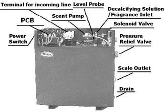
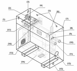
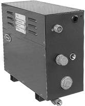
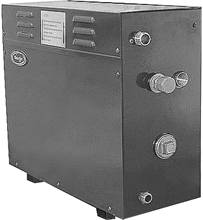
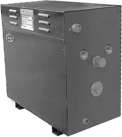
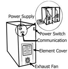
Steam Generator Parts (Figure 1)
(1) Power switch;
(2) Communication adapter; (3) Hole for Power supply cable; (4) Communication;
(5) Fixing holes; (6) Fragrance/Decalcifying Solution inlet; (7) Fragrance tube
inlet; (8) Water level probe; (9) Water inlet; (10) Pressure relief valve; (11)
Steam outlet; (12) Scale outlet; (13) Drain; (14) Transformer; (15) Exhaust
fan; (16) Terminal for incoming line; (17) Lights output.
Instructions of use
When
power supply to steam generator is switched on, a high beep will confirm the
supply and the screen displays the generator tank’s temperature.
There
are four different operation modes in the control unit: On/Off, Warmstart,
Timer/ Temperature and Light. The user can easily set the unit, making the
steam bathing more convenient with less energy consumption.
Press
On button on the control unit to activate the generator. When
generator is active, the control unit alternately displays time and temperature
in steam room.
Figure 2 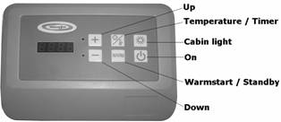
 On/Off Mode
When
the power switch of steam generator is turned on, press On/Off on control panel
to activate steam generator.
|
Once generator is activated, the
screen alternatively displays time and the set temperature in steam room.
|
 Warmstart / Standby Mode
Activate warmstart-mode
if the steam room is not used constantly.
During the
warmstart-mode the water in the steam generator tank is kept hot, with minimal
energy usage. The generator is able to produce steam shortly after pressing On
button on the control panel for the convenience of the user.
The default setting of
warmstart is of OFF-mode. To activate, press WARM button, the screen displays
OFF, press WARM button again to change to ON (= OH) mode.
To set / change
remaining warmstart time press and hold the WARM button for 4 seconds, then
press up or down buttons.
When warmstart is set to
00:00 and on ON-mode, auto drain feature will not be available.
When warmstart time
expires, cabin light and generator go off automatically.
To activate on-mode
again short press the WARM button to ON (= OH) mode.
 Temperature/ Timer
The temperature/timer
button can be used to switch between the temperature and session time.
When the power switch of steam
generator is turned on, the tank temperature is displayed. To set/change
temperature at desired level press up and down buttons directly. The default
set temperature is 450C degree. (maximum temperature possible is 600C degrees).
|
Under temperature control only
the temperature in the steam room will be kept in the preferred set
temperature with continuous discharge of steam. The generator will keep
running until it has been switched off manually. In this mode the light
also needs to be manually turned off.
|
If the temperature/timer
button is pressed, the remaining session time will be displayed. It can be
changed by pressing up and down buttons. The temperature / session time will be
saved as default settings if there is no buttons are pressed within 4 seconds
and the display will return to tank’s temperature until generator is activated.
Press On button and screen displays
00:00 then short press up or down button to set session time. When session time
is set 00:00 generator will keep running until warmstart time expires or it has
been manually switched off.
|
When under both temperature and
timer control and warmstart is of OFF-mode generator and cabin lights will be
switched off automatically when session time expires.
|

 Changing the values
Pressing up or down
button in control unit will increase or decrease the currently
displayed value. A value cannot be in- or decreased above or below its maximum
or minimum value.
The up and down buttons
are repetitive. Holding the up or down button will cause the value to in- or
decrease with an increased rate.
If no keys are pressed
within 4 seconds, changes in the values are confirmed.
If no keys are pressed
for 4 seconds, the display will automatically display the water tank
temperature.
 Cabin Light
The cabin light must be
switched on manually. It can be manually or automatically switched off:
a. If session time is set,
cabin light goes off automatically 15 minutes after session time expires.
b. If warmstart time is set
and warmstart is on On-mode, when warmstart time runs off, cabin lights switch
off automatically.
c. If warmstart time is set
to 00:00 and warmstart is on On-mode, however no session time is set, cabin
lights must be switched off manually.
d. When generator is under
temperature control only, cabin light must be manually switched off.
Key Lock
Lock and unlock the key
pad by pressing or holding On button for 4 seconds, the screen shows current
mode: ULOC = Unlock, LOC = LOCK, press either up or down buttons to change the
mode.
Only On/Off, warmstart
and cabin light buttons are usable when the control unit is locked. If other
buttons are pressed, relative current status is shown in the display.
The key
lock function is set automatically if it was left active during the previous
operation.
Auto Drain
The auto drain feature
automatically drains the water system after every use. The tank is flushed and
will remain empty until the steam generator is used again.
After the warmstart time
runs out, control unit automatically goes to Auto Drain mode. After hot water
drains, the generator’s tank will be flushed with cold water and then drains
again,which restrains scale from
forming on the inside surface of tank and heating elements . The draining
process will take about 10 minutes.
Steam Room Extractor Fan
The steam room extractor
fan feature will draw out the vaporous wastes from previous use. The extractor
fan will be activated automatically when session time expires.
Long press cabin light
button for 4 seconds, the control unit displays remaining steam room vaporous
wastes extracting time. To change the remaining exhaust time press up or down
button.
The default extractor
fan time is 10 minutes, maximum exhaust time can be set is 240 minutes. When
the extractor fan time is set 00:00, extractor fan on steam room will keep
operating until generator goes On-mode again.
Optional Feature
User can choose generator
with Scent Pump built in or a separate WinSpa Doser Unit. Figure 3
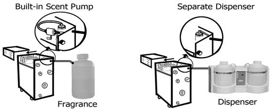
Built-in Scent Pump
Built-in Sent pump will
be operated when generator goes On-mode. Before switching generator on make
sure there is enough aroma in the aroma container. Never run the scent pump
dry.
Aroma oil will be filled
with each water recruitment of steam generator for 2 seconds. When session time
expires or generator is turned off, scent pump will turn off too. It will take
about 10 seconds for every 1 meter of pipeline for aroma liquid to reach the
pump.
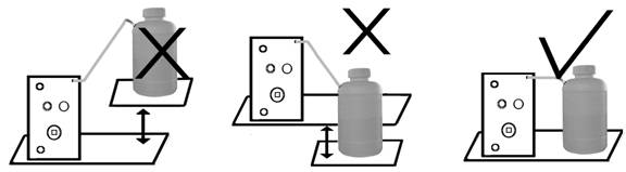
Fragrance container
should be placed at the same level with steam generator. Never place the
container upper or lower than generator. Make sure to fill the pipeline fully
with water using the injector in the pack.
When aroma oil is
changed, check that the pipeline is not broken and is full of liquid. It is
also recommended to wash the fragrance container between changes, especially
when using different fragrances.
Use only fragrance meant
for steam generator use. Follow the instructions in the fragrance packing.
Figure 4
Operating Steam
Room
1. Ensure power
supply to steam generator is switched on.
2. Ensure water
supply is turned on.
3. The steam room is
now ready to use, press On button on the control unit
to activate
the
generator.
Maintenance
1. Decalcification
Tap water contains impurities, for example lime, that
can cause calcium deposit and block the internal parts of the steam generator.
To prevent this and prolong the lifetime of steam generator it is recommended
to have a water filter and water softener. They are connected to the water
source of steam generator’s water inlet.
Follow these
guidelines to perform preventative maintenance of steam generator.
|

|
Figure 5 
|
|
①. Turn on the generator and press WARM
button to switch on warmstart mode and wait until water inside generator tank
starts to boil. Disconnect steam generator from main power supply before
opening generator’s cover. Only licensed electrician or professional
maintenance person can open covers and do cleaning.
|
②. Use adjustable wrench to remove the tube cap of the
scale remover inlet. Before opening, make sure that the generator is off. Cool
down the angled tube with wet cloth if needed.
③ Pour
the solution through tundish into the water tank. Do it slowly enough to
prevent solution to splash into the generator.
④ Close the cap firmly and let the solution stay in the
tank for 30 minutes. Do not switch the generator on.
⑤ Drain the water tank by activating the generator for
2 minutes. Press On button again manually to start auto drain.
⑥ Repeat
the step 5 two more times.
Use Decalcifying Solution as
follows:
|
Steam Generator (kW)
|
Decalcifying Solution
(ml)
|
|
3 - 8
|
250
|
|
10-18
|
500
|
For steam generators in commercial use (over 5 hours
continuously daily) additional service plan is recommended three times a year.
Please contact your service center for details.
Frequency for decalcification:
Unit dH where 1 dH is 10 mg calcium in 1
liter of water
< 30 dH = very soft water,
decalcification every 500 operation hours
3-60 dH = soft water,
decalcification every 100 operation hours
6-90 dH = hard water,
decalcification every 50 operation hours
9-180 dH = very hard water,
decalcification every 30 operation hours
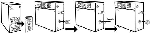
2. Level probes cleaning
Tips of WinSpa Water level probes are
protected by a patented coating from scale attaching. For generator in
commercial use (over 5 hours continuously daily), service plan is recommended minimum 4 times
a year.
a.
Disconnect steam
generator from main supply before opening generator’s covers. Only licensed
electrician or professional maintenance person can open covers and do cleaning.
b.
Use adjustable wrench
to deattach 2 wires from level probes. Make sure that when connecting wires
back, wires are connected to right probe.
c.
Use adjustable wrench
to remove level probe. Clean tip of the pins from impurities using sandpaper
and replace coatings on tip in every cleaning service! Don’t damage plastic
coating on pins. If coating is damaged, replace level sensor. Tighten level
sensor by hands and use adjustable wrench only for final tightening.
3.Tank cleaning
a. Disconnect steam generator from
main supply before opening generator’s covers. Only licensed electrician or
professional maintenance person can open covers and do cleaning.
b.
Open side cover of
heating elements.
a)
Disconnect heating
elements and exhaust fan.
b)
Remove heating elements
and clean deposits from the elements.
c.
Open the scale outlet
plug on side of generator using adjustable wrench.
a)
Remove deposits from
bottom and sides of the tank and wash away deposits. Don’t use auto drain valve
since big particles can block the valve.
b)
Attach the plug and use
Teflon pipe seal if needed.
c)
Screws in the heating
elements. Make sure that heating elements and exhaust fan are connected
correctly. Figure 6
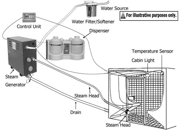
Assembly and Installation
1). Location of the steam generator has to
be near the steam room. Place it within 7.5 meters to the steam room.
2). Steam generator has to be installed
outside the steam room.
3). The steam generator must not be installed outdoors
or areas that may damage the unit due to climate conditions.
4). Do not install the steam generator or plumbing
lines in unheated attic or any locations where water could freeze.
5). The steam generator must not be installed in areas
near flammable or corrosive materials or chemicals such as gasoline, paint
thinners, chlorine or the like.
6). Provide a level surface to install steam
generator. Side hole slots are provided for wall mounting. Make sure that the
steam generator is secured and is level when mounted on the wall.
7). The steam generator has to be installed
in an upright position only.
8). Install water filter and softener or
alike when necessary.
9). Leave enough space for service and
maintenance of the generator.
Figure 7
Plumbing
All
plumbing has to be installed by a licensed qualified plumber. Plumbing should
be in accordance with national or local codes. Use unions for piping
connections. Use only 12mm (1/2”) brass piping or copper tubing. Never use black or galvanized pipe for the plumbing as it can easily crack or damage.
Water Supply
Provide
a shut off valve on the water source for the steam generator. Turn off the
inlet water line before installing the unit. Recommended water pressure is 1 to
3 bar and maximum water pressure without water filter/softener is 4 bar. Water
softener is recommend to use.
Steam Outlet
The
steam must move in a continuous flow to the steam room. Do not install valves
on the steam line. Use insulated, rated 1200C or higher, brass pipe or copper tubing for steam line to connect to the steam head as permitted by codes. Slope the steam line height by 20mm per meter towards the steam head to avoid trapping of the condensate and eliminate steam trap that blocks the flow of the steam. Never use bends wherever possible. But when
necessary always install sweeping bends to allow easy flow of steam.
For
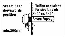
best operating results install a 20mm (3/4”) line. Two steam outlets are required for generator up to 18kW, however, for generators up to 6kw a 12mm (1/2”) line will suffice.
Pressure Relief Valve
The
pressure relief valve activates when there is an overpressure in the steam
line. It automatically opens and releases the pressure steam. When this
happens, please check your steam line for servicing.
|
Steam Head
Figure
8
Install steam head in location to avoid
body contact and scalding. The steam head must be installed with outlet
facing down to floor. Seal thread using Teflon tape and do not over tighten.
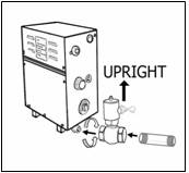
Drain
|
|
Drain
valve is installed inside steam generators over 6.0kW, for generators below
6.0kW a drain valve is provide for maintenance. Set drain connection for your
steam generator according to national or local plumbing requirements. Make sure
the valve is installed upright. When connections are made always use two
wrenches/spanners.
|
Attaching Autodrain Figure 9
(for 3.0~ 6.0kw steam generator)
1.
Attach
the autodrain to the outlet. Make sure the valve is installed upright. Union is recommended when connecting pipeline .
2.
Plug
the wire into the plinth on circuit board of steam generator.
|
|
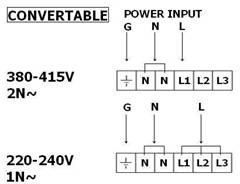
Power Wiring
Only
a qualified electrician should do the Electrical wiring connections.
Check
the power supply before installing your unit. Single Phase connection, a 220 –
240V supplied is required. Use two-wire supply source and equipment grounding
wire for single phase connection. Check size of wires in Ampere Chart in
accordance with the National Electrical Code and local electrical code.
The
installation must include switch for all pole disconnection. Circuit breaker
with 3mm control gap is recommended.
Technical Data
|
Model
|
kW
|
Steam Room Volume (m3)
|
Voltage
(V)
|
Current
(A)
|
Phase
|
Wire Size mm2
|
Size of Steam Room (mm)
|
|
Width
|
Depth
|
Height
|
|
WS 30
|
3.0
|
3 max
|
220-240 /
|
14
|
1N /
|
4.0
|
430
|
170
|
360
|
|
380-415
|
8
|
2N
|
2.5
|
|
WS 40
|
4.0
|
4 max
|
220-240 /
|
17
|
1N /
|
4.0
|
430
|
170
|
360
|
|
380-415
|
10
|
2N
|
2.5
|
|
WS 50
|
5.0
|
3-6
|
220-240 /
|
22
|
1N /
|
4.0
|
430
|
170
|
360
|
|
380-415
|
8
|
2N
|
2.5
|
|
WS 60
|
6.0
|
3-10
|
220-240 /
|
26
|
1N /
|
6.0
|
430
|
170
|
360
|
|
380-415
|
9
|
2N
|
2.5
|
|
WS 60
|
6.0
|
3-10
|
220-240 /
|
26
|
1N /
|
6.0
|
480
|
200
|
420
|
|
380-415
|
9
|
3N
|
2.5
|
|
WS 80
|
8.0
|
8-20
|
220-240 /
|
37
|
1N /
|
8.0
|
480
|
200
|
420
|
|
380-415
|
19
|
3N
|
4.0
|
|
WS 100
|
10.0
|
9-22
|
220-240 /
|
46
|
1N /
|
10.0
|
480
|
200
|
420
|
|
380-415
|
23
|
3N
|
6.0
|
|
WS 120
|
12.0
|
15-28
|
380-415
|
28
|
3N
|
6.0
|
480
|
200
|
420
|
|
WS 120
|
12.0
|
15-28
|
380-415
|
28
|
3N
|
6.0
|
480
|
250
|
420
|
|
WS 150
|
15.0
|
22-40
|
380-415
|
19
|
3N
|
4.0
|
480
|
250
|
420
|
|
WS 180
|
18.0
|
26-45
|
380-415
|
28
|
3N
|
336.0
|
480
|
250
|
420
|
NOTE:
This table is for steam rooms built in with light
walls (tempered glass or acrylic). Steam rooms with thick walls or ventilation,
please use higher kilowatt steam generators.
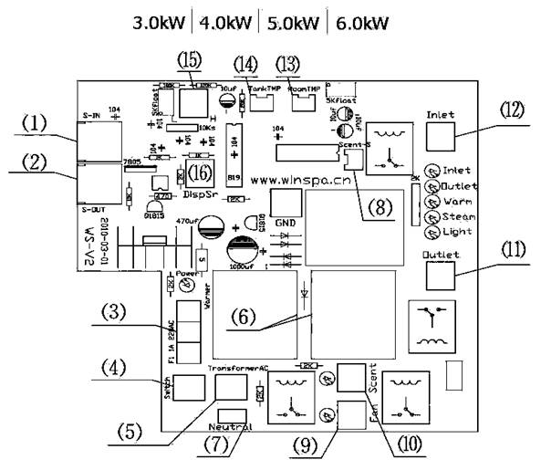
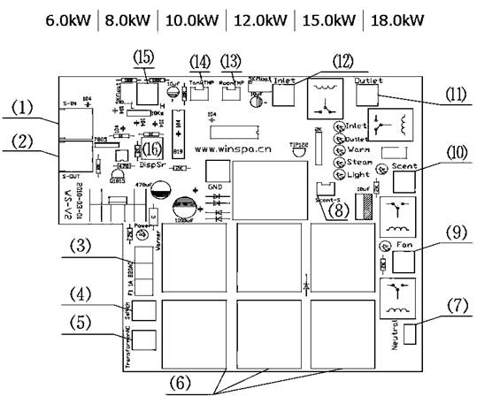
Electrical Diagrams (Figure 10)
Circuit Card
(1)=Communication;
(2)=Communication adapter; (3)=Fuse; (4)=Main Switch; (5)=Transformer;
(6)=Relays for heating elements; (7)=Neutral wire input; (8)=Level sensor for
built-in Scent Pump; (9)=Steam Room Exhaust Fan; (10)=Interface for built-in
Scent Pump; (11)=Drain; (12)=Solenoid Valve; (13)=Steam Room Temperature
sensor; (14)=Tank Temperature sensor; (15)=Water Level Probes; (16)= Dispenser
Unit Control
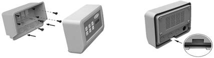
Connection of WinSpa Control to the PCB (Figure 11):
Installing Control Unit
Mount
the steam control unit on an accessible area outside the steam room. It is
recommended not to place the steam control near to showers or similar wet
places. Do not install the control unit inside the steam room! Never attempt to
modify or to fix the steam control. Ask your licensed technician or your
nearest dealer service center for repair. The control cable is recommended not
longer than 30 meters. Figure 12
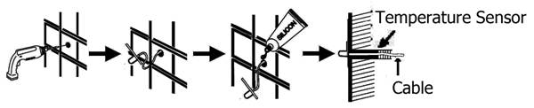
Installing the Temperature Sensor
Before
installation the generator must be switched off from main power supply.
The
temperature sensor comes along with the WinSpa steam generator. It is
recommended to use only WinSpa temperature sensor with WinSpa generator as it
may otherwise not function correctly. Temperature sensor wiring should not be
routed near power cables or hot areas as it may cause electronic interference
or damage to the wires.
1. The temperature sensor
has to be installed:
a. On a surface where there is no
obstruction below it.
b. Height has to be 1.5-1.7 meters
above the floor.
c. It should be away
from the steam head so that the steam will not hit the sensor directly.
The sensor has an
integrated 9-meter cable. If longer cable is needed, please consult your WinSpa
technician.
2. A 4mm hole is required to insert the temperature sensor. Do not create bigger or smaller hole. Clean the hole before inserting the sensor.
3. Either make a hole in
the cable lead-in on back of control unit to pull the cable through, or plug
the cable into the plinth on PCB inside generator. See figure 10.
4. Pull the temperature
sensor through the steam room wall. Do not apply staples or other material that
may damage the cable.
5. Insert the temperature
sensor into the steam room. Screw or glue the sensor to the wall
6. Apply silicone sealant
on the hole in the wall to create a moisture seal. Make sure there is no trace
of silicone on the sensor as it may interfere its reading. Figure 13
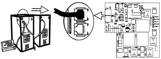
Steam Generator Series Connection (Figure 14)
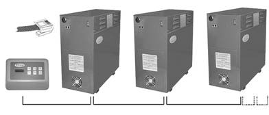
Control Master Slave
1 Slave 2 …….
NOTE! In the event of faulty operation occurs in any one of
the slave units, a warning beep will alarm the user from the faulty generator,
however the rest of the generators can operate normally.
Troubleshooting
If an error occurs, the steam generator should be
switched off. There will be a warning beep sound to alarm the user every 2
seconds. There will be 3 different beep sounds.
See below Sound Indentification:
.
|
WINSPA Steam Generator Fault Code
Table
|
|
Code
|
Sound
|
Fault description
|
Maintenance
recommendations
|
|
E1
|
One Long Ring
|
Water tank temperature is too high,
the heating element may be in the dry burning
|
Power off immediatly & check
|
|
E2
|
Two Long Ring
|
Water inlet problem
|
Check water, pipe and the water
inlet electromagnetic valve
|
|
E3
|
Three Short Ring
|
Water outlet problem
|
Check the drainage pipe and a
drainage valve
|
|
E4
|
Four Short Ring
|
Short circuit on higher leg of water
level probe
|
Check the circuit board, see if any
touch between the probe heating element or tank,cleaning tank scale
|
|
E5
|
Five Short Ring
|
The scale is too much on higher leg
of water level probe
|
Clean the scale on the water level
probe
|
|
E6
|
Four Short Ring
|
Short circuit on lower leg of water
level probe
|
Check the circuit board, see if any
touch between the probe heating element or tank,cleaning tank scale
|
|
E7
|
Five Short Ring
|
The scale is too much on lower leg
of water level probe
|
Clean the scale on the water level
probe
|
|
{No}
|
{One Short Ring}
|
{No fault, the power-on completion}
|
|
IMPORTANT! only a qualified electrician or
maintenance personnel are allowed to make the service operations and repairs!
Checking and Fault-finding
In the event of faulty operation, first check the
following:
l
Are the control panel
and steam generator connected properly?
l
Is the steam generator
correctly installed in accordance with these instructions?
l
Dose the drainage pipe
slope down properly towards the waste outlet?
l
Is the filter clogged?
To clean the filter, disconnected the feed pipe, remove the filter and rinse it
free from particles of calcium carbonate and other deposits.
l
Are there any sharp
bends in the steam pipe? (the minimum permitted radius of bends is 50mm,2”)
l
Does the construction
and ventilation of the steam room comply with instructions?
Followings are for a quick check:
After generator is powered on, the display on control
panel shows  .
.
Cause:
The temperature sensor on water tank is loose connected.
Solution: Disconnect the power supply to steam generator, open
the front cover of the generator. Tighten the spade connector on the tank using
a cross screwdriver.
The display on control panel shows  and
time alternatively:
and
time alternatively:
Cause:
The steamroom temperature sensor is loose connected to the control panel – or
to the main circuit card (steamroom temperature sensor can be either connected
to control panel or to the main circuit card inside the steam generator).
Solution: Disconnect it and plug it in again properly.
Cause:
the steamroom temperature sensor is faulty.
Solution: Replace a temperature sensor.
Chicklist
Steam generator buzzes all the time
|
Causes
|
Solution
|
|
Tap water
pressure is too low and/or the filter is clogged which cause unstable
incoming water flow
|
Increase
the water pressure or clean the filter
|
|
Solenoid
valve for water supply has stuck or been defective.
|
Clean
or replace the solenoid valve
|
|
Malfunction
CPU of main circuit board is defective
|
Important! Always keep the fan inside generator working to cool
the air around CPU and replace the faulty component
|
|
The
water level probes are coved by excessive calcium carbonate deposits, or the
internal diameter of the steam pipe is considerably reduced which may cause a
too great high temperature in water tank, or heating elements are drying
burn.
|
Clean
or replace the level probes
Replace
the pipe or the pipe joint which is causing the reduction; refer to Steam
Outlet on page 12
|
|
Drainage
valve has stuck by calcium carbonate deposits or been defective
|
Clean
or replace the drain valve
|
The steam room
maintains the desired temperature (40-500C, 105-1220F), but no steam is produced
|
Causes
|
Solution
|
|
Cause: Insufficient ventilation in the steam room
|
Increase
ventilation. The ventilation is insufficient if less than 10-20 cubic
meters(13-28 cub.yd) of air per person per hour is evacuated via the outlet
vent.
|
|
Cause: The air coming into the steam room is too warm
|
Reduce
the intake air temperature to 350C (950F)
|
|
Cause: The ambient temperature is higher that 350C (950F)
|
Ensure
that the ambient temperature does not exceed 350C (950F)
|
|
Cause: The thermometer is faulty or wrongly placed.
|
The
thermometer should be placed approximately 170cm (67”) above floor level and as far away from the steam jet as possible.
|
Erratic steam production right from the start.
|
Causes
|
Solution
|
|
Cause: The steamroom thermostat sensor
is
wrongly placed in relation to the steam jet.
See
TEST 1.
|
Move
the sensor or alter the direction of the steam jet.
|
|
Cause: Calcium carbonate or other foreign
bodies
in the filter.
|
Remove
and clean the filer.
|
The steam room requires an abnormally long time to
heat up
|
Causes
|
Solution
|
|
Cause: The generator is not powerful enough. See Table on Page
13
|
Replace
the steam generator with one with a higher heat output.
|
|
Cause: Excessive ventilation in the steam room.
|
Reduce
the ventilation to evacuate 10-20 cubic meters (13-26 cub.yd) of air per
person per hour.
|
|
Cause: The ambient temperature is lower than 150C (590F)
|
Increase
the ambient temperature or replace the steam generator with a more powerful
one
|
|
Cause: Heating element is broken.
|
Replace
heating elements.
|
|
Cause: The steam room thermostat sensor is too close to the
steam jet. See TEST 1.
|
Move
the sensor or change the direction of the steam jet.
|
Neither steam nor heat is generated in the steam room
|
Causes
|
Solution
|
|
Cause: Control box is incorrectly set
|
Check
the time and temperature on the control box
|
|
Cause: The water is not reaching the steam generator.
|
Open
the tap connected to the piping to allow incoming water to flow into the
steam generator.
|
|
Cause: The filter is clogged
|
Remove
the filter and clean off any metal filings or other foreign bodies.
|
|
Cause: The solenoid valve for water supply has stuck or been
defective.
|
Remove
the solenoid valve and clean off any metal filings or other foreign bodies.
Or replace a solenoid valve.
|
|
Cause: Excessive calcium carbonate deposits in the steam
generator's water tank.
|
Clean
the water tank by following steps of Tank Cleaning on page 10
|
|
Cause: Malfunction in the circuit board or control panel.
|
Replace
the faulty component.
|
|
Cause: The steam generator is wired up for the wrong voltage
|
Check
the voltage and the connection to the generator. See Figure 10 on page 14.
|
|
Cause: The heating element is broken
|
Replace
the defective heating elements.
|
A continuous trickle of hot water from the steam
generator’s drainage pipe.
|
Causes
|
Solution
|
|
Cause: The drainage valve has stuck or been defective.
|
Disconnect
the power supply to steam generator, remove the drainage valve and clean it.
If the fault persists after cleaning, replace a drainage valve.
|
Hot water comes out of the steam head in spurts or in
a slight, even flow mixed with steam.
|
Causes
|
Solution
|
|
Cause: Small water pocket along the steam pipe.
|
Eliminate
the water pocket by sloping down the steam pipe to steam room.
|
|
Cause: The steam pipe is uninsulated along too great a portion
of its length.
|
Insulate
the steam pipe.
|
Pressure Relief Valve opens / is activated.
|
Causes
|
Solution
|
|
Cause: The steam pipe is blocked.
|
Remove
the blockage.
|
|
Cause: The internal diameter of the steam pipe is considerably
reduced.
|
Replace
the pipe or the pipe joint which is causing the reduction; refer to Steam
Outlet on page 12
|
|
Cause: Sharp bends along the steam pipe. See TEST 2.
|
Take
out the sharp bends in the pipe. Bends are to be gently rounded (minimum
radius 50mm, 2").
|
|
Cause: Large water pocket somewhere along the steam pipe. See
TEST 2
|
Adjust
the steam pipe to eliminate the water pocket.
|
|
Cause: Excessive calcium carbonate deposits in the steam
generator's reservoir.
|
Clean
the water tank. See Tank Cleaning on page 10
|
TEST 1
Temperature sensor test.
Soak a small towel in cold water. Hang the wet towel
over the thermostat sensor. If, within 20 minutes, the steam generator has
started to produce steam continuously, the equipment is not defective, but the
thermostat sensor is located in an unsuitable position, or the thermostat
itself is faulty. If steam production does not begin, use the checklist to find
out the cause.
TEST 2
Steam pipe test if the pressure relief valve is
activated.
Disconnect the steam pipe from steam generator. Start the
generator and let it remain on for about 10 minutes. If the pressure relief
valve is not activated during this test, there is a blockage along the steam
pipe which is preventing the passage of steam. Take the necessary steps
according to the information in the checklist.
TEST 3
Steam generator beeps all the time but no faulty parts
can be found.
Switch off the steam generator by pressing on/off on
control panel after operating 20 minutes or when beeps, the display shows
current temperature of the water tank. use the checklist to find out the cause.
Limited Warranty - WS Steam Generator
Two-Year
Warranty
WinSpa warrants
the control system, water tank and transformer for a period of two year from
the original purchase date. Warranty on the factory installed spare parts
specially covers the heating elements, inlet valve, drainage valve and exhaust
fan for a period of 6 months from the original purchase date. Refurbished
parts may be used to satisfy warranty replacement of electrical and mechanical
parts.
WinSpa reserves
the right to inspect or designate a person to inspect any part that is claimed
to be defective and covered by this warranty.
Any and all
additional cost and fees including shipping, delivery, freight, set-up,
installation, upgrade fees and disposal charges will be the responsibility of
the steam generator owner.
Acts
Invalidating Warranty
Warranty
conditional upon proper installation under this instruction manual and regular
basic maintenance, including regular removal of calcium and cleaning the water
tank and electrodes.
This warranty is
void if the steam generator has been subjected to alterations, neglect, misuse
or abuse; if any repairs have been attempted by anyone other than an authorized
serviced representative; or if failure caused by accident, acts of nature or
other causes beyond the control of Winspa.
Disclaimers
WinSpa shall not
be held liable for injury or loss of use of your steam generator or other
incidental and consequential cost, expense or damage, whether incidental or
consequential, arising out of any defect covered by this Limited Warranty,
including, without limitation, loss of use of the steam generator and cost of
removal of defective product, even if WinSpa has been advised of the
possibility of such damage. In no event shall WinSpa be liable for any reason
or cause in excess of the amount paid for the product by the dealer.
Coverage under this Limited Warranty shall commence as
of the original date of purchase or as otherwise outlined above and the
duration of such coverage shall not extend for any reason whatsoever beyond the
stated time periods. No other warranties, written or implied, are valid.
To apply for warranty following details must be
forwarded to WinSpa by email within 30 days of installation:
1.
Model number of steam
generator
2.
Serial number of steam
generator
3.
Date installed.
4.
Name of installer
5.
Name of customer
6.
Water filter installed
( Yes / No )
Table of Spare Parts Replacement
|
Spare Parts#
|
Model
|
Series No.
|
Replacement Date
|
|
Main
Circuit Card (PCB)
|
WS_____
|
|
_____/_____/_____
|
|
Control
Panel
|
WS_____
|
|
_____/_____/_____
|
|
Water
Level Probe
|
WS_____
|
|
_____/_____/_____
|
|
Steamroom
Temperature Sensor
|
WS_____
|
|
_____/_____/_____
|
|
Heating
Element
|
WS_____
|
|
_____/_____/_____
|
|
Transformer
|
WS_____
|
|
_____/_____/_____
|
|
Water
Inlet Valve
|
WS_____
|
|
_____/_____/_____
|
|
Drainage
Valve
|
WS_____
|
|
_____/_____/_____
|
|
Pressure
Relief Valve
|
WS_____
|
|
_____/_____/_____
|
|
Exhaust
Fan
|
WS_____
|
|
_____/_____/_____
|
|
Fragrance
Feeding Pump
|
WS_____
|
|
_____/_____/_____
|
|
Steamroom
Exhaust Fan
|
WS_____
|
|
_____/_____/_____
|
|
Others______________________
|
WS_____
|
|
_____/_____/_____
|

www.winspa.cn
Subject to change without
prior notice